
Jump to a Section:
Introduction — What Is Pressure Vessel PWHT and Why It Matters
Section 1 — What Is Post Weld Heat Treatment?
Section 2 — When Is Pressure Vessel PWHT Required Under ASME Section VIII?
Section 3 — How Is On-Site Pressure Vessel PWHT Executed? A Step-by-Step Breakdown
Section 4 — What Are the Temperature and Rate Specifications for Pressure Vessel PWHT?
Section 5 — How Does Wall Thickness Affect Pressure Vessel PWHT?
Section 6 — On-Site Direct Gas Fire vs Shop Furnace — Which Is Right for Your Vessel?
Section 7 — What Does Experience Actually Look Like in Pressure Vessel Heat Treating?
Section 8 — What Are GCC’s Technician Certification Standards?
Section 9 — What Happens When You Call Gulf Coast Combustion?
Frequently Asked Questions
Get an Instant Estimate →
Get a Free Quote →
Post Weld Heat Treatment Explained — What It Is, How It Works, and What to Expect from a Professional Heat Treating Partner
Published by Gulf Coast Combustion | Spring, TX | gulfcoastcombustion.com | 713-425-3773
What Is Pressure Vessel PWHT and When Is It Required?
Post weld heat treatment (PWHT) for carbon steel pressure vessels is a controlled thermal stress relief process executed between 1,100°F and 1,200°F per ASME Section VIII UCS-56, required based on wall thickness, material chemistry, service conditions, and client or WPS specifications.
Quick Reference
| What | Controlled heating and cooling of a pressure vessel after welding to relieve residual stresses in the steel and weld heat affected zone. |
| Who | Required for fabricators building carbon steel pressure vessels to ASME Section VIII Division 1 when wall thickness, material type, or service conditions trigger the requirement under UCS-56. |
| When | After welding is complete, before the vessel enters service. PWHT is code-required — not discretionary. Many oil & gas and petrochemical clients specify requirements tighter than ASME minimums. |
| Where | On-site at your facility using direct gas fire combustion — no transport, no heavy haul, no furnace required. Gulf Coast Combustion mobilizes anywhere in the U.S. for vessels from 10 feet to 120 feet and beyond. |
| Why | Welding locks residual stress into the steel. In high-pressure, thick-walled vessels, those stresses can cause stress corrosion cracking and compromise weld integrity over time. PWHT relieves them — with full documentation proving the process was performed to code. |
If you fabricate pressure vessels for oil & gas, chemical processing, or petrochemical applications, post weld heat treatment isn’t optional. It’s a mandatory step in the fabrication process — required by code, specified by your clients, and critical to the long-term integrity of every vessel you build.
But pressure vessel PWHT is also one of the most misunderstood steps in the fabrication process. Many fabricators know they need it without fully understanding what’s happening inside the steel, why the process parameters matter, or what separates a properly executed heat treatment from one that falls short.
This guide explains it all — in plain language, from the most experienced on-site pressure vessel PWHT operation in the country.
Talk to the Owner Directly
Owner, Gulf Coast Combustion
Call or text — James answers personally
Office: 713-425-3773 | james@gulfcoastcombustion.com
No receptionist. No call queue. No waiting on a callback from someone who wasn’t on the last job.
SECTION 1: WHAT IS POST WELD HEAT TREATMENT?
Post weld heat treatment is the controlled heating and cooling of a pressure vessel — or a specific weld area — after welding is complete. The goal is to relieve the residual stresses introduced into the steel during the welding process.
When steel is welded, the heat of the welding arc creates a heat affected zone (HAZ) around the weld. As the weld cools unevenly, it contracts at different rates across the material — creating internal stresses locked into the steel. In high-pressure, thick-walled vessels these residual stresses can compromise the structural integrity of the weld and the vessel itself.
PWHT eliminates those stresses by bringing the entire vessel — or the affected area — up to a specific elevated temperature, holding it there long enough for the steel to equalize and relax, and then cooling it in a controlled manner.
The result is a vessel with improved mechanical properties, reduced risk of stress corrosion cracking, and documentation that proves the process was performed to code.
| Stage | What’s Happening | Why It Matters |
|---|---|---|
| Controlled heat-up | Temperature rises at a calculated rate based on wall thickness | Prevents thermal shock and uneven expansion in thick-walled vessels |
| Soak / hold | Vessel held at temperature long enough for steel to equalize | Residual stresses relax; mechanical properties improve across the HAZ |
| Controlled cool-down | Temperature drops at a calculated rate until 800°F, then free air | Prevents re-introduction of stresses from rapid temperature change |
| Documentation | Strip chart recorder traces every phase of the cycle | Permanent record that code requirements were met — required by ASME Section VIII |
By the Numbers — ASME Section VIII (UCS-56)
GCC Standard Parameters
1,150°F
Standard Soak Temp ±50°F
400°F/hr
Max Heat-Up Rate ÷ Wall Thickness
250°F
Max Temp Differential During Soak
800°F
Free Air Cooling Below
Most steels requiring PWHT are brought up with a controlled rate of heating, soaked at a desired time and temperature, then brought down to a low enough temperature at a controlled rate of cooling — creating a specific density and tensile strength in the weld and heat affected zone. Every parameter is calculated, monitored, and documented. Nothing is guessed.
Estimator’s Resource
On-Site PWHT vs. Off-Site Furnace —
Full Cost Breakdown
Furnace quotes leave out transport, permits, rigging, and the return trip. Before you sign a purchase order, see every line item most fabricators don’t price in until it’s too late.
From the Field — James Benefield, GCC Owner
After performing on-site PWHT on hundreds of pressure vessels since 2014, one thing comes up on almost every first-time job:
Vessel placement has to match the execution plan before we arrive. The plan specifies exactly which manways the burners go through and at what orientation. If the vessel is set wrong, we’re problem-solving on job day instead of executing.
The earlier we see your vessel in position, the cleaner the job runs.
SECTION 2: WHEN IS PRESSURE VESSEL PWHT REQUIRED UNDER ASME SECTION VIII?
PWHT is required under ASME Section VIII UCS-56 based on material type, wall thickness, service conditions, and client or WPS specifications. Carbon steel and low alloy steel pressure vessels are the most common applications. Requirements are governed by ASME BPVC Section VIII Division 1 and may exceed code minimums when client specifications demand it.
PWHT requirements for pressure vessels are governed by ASME Boiler and Pressure Vessel Code Section VIII Division 1, specifically UCS-56. Requirements are triggered by several factors:
Material Type
Carbon steels and low alloy steels are the most common materials requiring PWHT under ASME UCS-56.
Wall Thickness
Above certain thickness thresholds PWHT becomes mandatory regardless of other factors.
Service Conditions
Vessels for lethal service, high temperature service, or specific corrosive environments have additional requirements.
Client Specifications
Many fabricators and end clients specify requirements more stringent than the ASME minimum.
The governing code establishes minimum requirements. In practice, fabricators building vessels for major oil & gas and petrochemical operators frequently work to customer-specified requirements that go beyond what ASME mandates. Gulf Coast Combustion builds every execution plan to meet or exceed both the governing code AND any customer-specific requirements.
SECTION 3: HOW IS ON-SITE PRESSURE VESSEL PWHT EXECUTED? A STEP-BY-STEP BREAKDOWN
On-site pressure vessel PWHT involves 10 sequential steps: execution plan development, equipment mobilization, insulation wrap, thermocouple attachment, burner installation, controlled heat-up, soak at 1,150°F ±50°F, controlled cooldown, strip out, and full documentation package — all executed per ASME Section VIII UCS-56.
Understanding what actually happens during a PWHT job helps fabricators plan better, communicate more effectively with their heat treating vendor, and evaluate whether a job was done correctly.
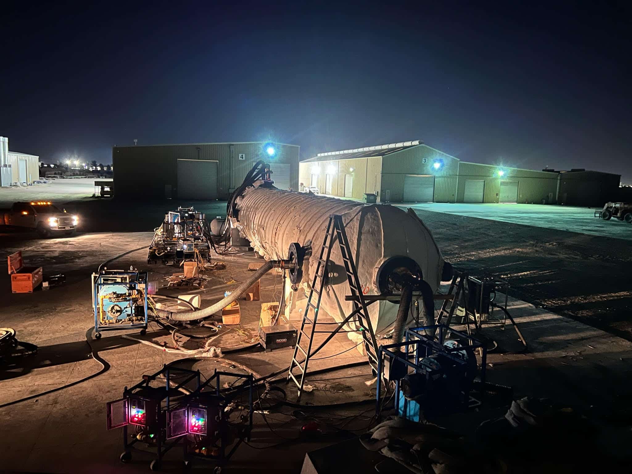
See it for yourself below — a 621,000 lb vessel, wrapped and fired on-site. Direct gas fire combustion, start to finish in 90 seconds.
Here is how Gulf Coast Combustion executes an on-site pressure vessel PWHT from start to finish:
Execution Plan Development
Before GCC ever arrives on site, a custom execution plan is developed for each specific vessel. This plan documents the vessel ID, governing code, soak temperature, minimum soak time, thermocouple placement, burner assignment, heating and cooling rates, and all technical specifications. The execution plan is submitted to the client for approval before work begins. GCC management and quality control must approve all heat cycles and setups prior to PWHT start.
Mobilization and Equipment Staging
GCC mobilizes to your facility with all necessary equipment — high velocity gas combustion systems, blowers, gas trains, thermocouple attachment units, strip chart recorders, insulation, and consumables. Equipment is offloaded and staged around the vessel. All pieces to be heat treated must be cleaned and properly supported before GCC begins setup.
Insulation Wrap
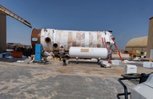
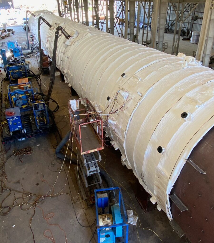
The vessel is wrapped carefully and methodically in 1″ 8lb Kaowool ceramic fiber blanket insulation. Insulation is applied around the entire vessel surface with a 3″ overlap to account for thermal expansion, and secured with carbon steel banding straps, stud pins, iron wire, or wire rod mesh. All nozzles and attachments are insulated for thermal growth. This process transforms the vessel into its own furnace.
Thermocouple Attachment
Thermocouples are attached to the vessel surface using a TAU capacitor discharge spot welder — not clips, bands, or nuts. This method welds Type K chromel/alumel thermocouple wire directly to the vessel surface so that the steel itself becomes the thermocouple junction. Other attachment methods can produce temperature reading errors of up to 60°C, which is unacceptable on a code job. Thermocouple placement shall not exceed intervals greater than 15 feet apart along the vessel surface.
Why Attachment Method Matters
Clips, banding wire, and welded nuts hold the thermocouple junction away from the steel surface. Under PWHT conditions — with the vessel expanding and the insulation blanket pressing inward — that gap produces temperature readings that don’t reflect what the steel is actually doing. The error can reach 60°C. On a code job, that’s not acceptable. GCC welds Type K wire directly to the vessel surface with a TAU capacitor discharge spot welder, making the steel itself the measurement point. Placement follows a grid pattern with spacing never exceeding 15-foot intervals. Heavy forged nozzles and high-mass features get their own dedicated thermocouples.
Combustion Equipment Installation
High velocity gas burners are installed through available nozzles and manways, positioned to ensure uniform heat distribution throughout the vessel. GCC utilizes gas train consoles with up to 8 million BTU capacity. The number and placement of burners is calculated based on the vessel’s weight and wall thickness to achieve uniform heating across the entire vessel.
The Heat Cycle
Temperature recording begins at 300°F. Below 800°F a moderate rate of heating is applied. Above 800°F the rate of heating is controlled at 400°F per hour divided by the governing wall thickness — and shall never exceed 400°F per hour regardless of wall thickness.
During heating above 800°F there shall be no temperature variation greater than 250°F within any 15-foot interval along the vessel length.
For example: On a vessel with 1″ governing wall thickness the maximum heat-up rate above 800°F is 400°F per hour. On a vessel with 2″ governing wall thickness the maximum rate is 200°F per hour. As wall thickness increases the heat-up rate becomes more controlled and deliberate.
Soak Period
Soak begins when all thermocouples reach a minimum of 1,100°F. The maximum soak temperature is 1,200°F. GCC’s standard soak parameters are 1,150°F ±50°F. Hold time is determined by governing wall thickness per ASME standards — a minimum of 1 hour per inch for the first 2 inches, plus 15 minutes for each additional inch beyond 2 inches. During the soak period the temperature differential between the highest and lowest reading thermocouple must not exceed 250°F.
Controlled Cooling
After the soak period is complete, cooling is controlled at 500°F per hour divided by the governing wall thickness — and shall never exceed 500°F per hour regardless of wall thickness. Below 800°F the vessel may cool freely in still air without thermocouple monitoring. Burners remain in place until the vessel is cool enough to strip safely.
Strip Out
Once the vessel has cooled sufficiently, insulation is removed, thermocouples are detached and attachment areas dressed, and all combustion equipment is removed. GCC loads all equipment back on the trailer and prepares the documentation package.
Documentation Package
Every GCC job is completed with a full documentation package: Heat Treatment Record (HTR) — documents all job details, personnel, hours, equipment, consumables, and procedure reference; Strip Chart Recorder Trace — the physical temperature-time record for every thermocouple channel throughout the entire cycle; Recorder Calibration Certificate — NIST traceable annual calibration certificate; Execution Plan — the pre-approved technical plan specific to that vessel. All paperwork is completed in black ink, legible, with proper dates and identification numbers.
Wondering how long the full process takes from setup to pack-out? Here’s a complete breakdown of the on-site PWHT timeline. For a detailed Q&A on how the process actually works in the field, see What Engineers Actually Want to Know About On-Site Pressure Vessel PWHT.
On-Site PWHT Pricing
See What Your Job Costs — Instantly.
Enter your vessel specs and get a budgetary estimate in seconds — built from GCC’s actual job data. No email required.
As Featured In
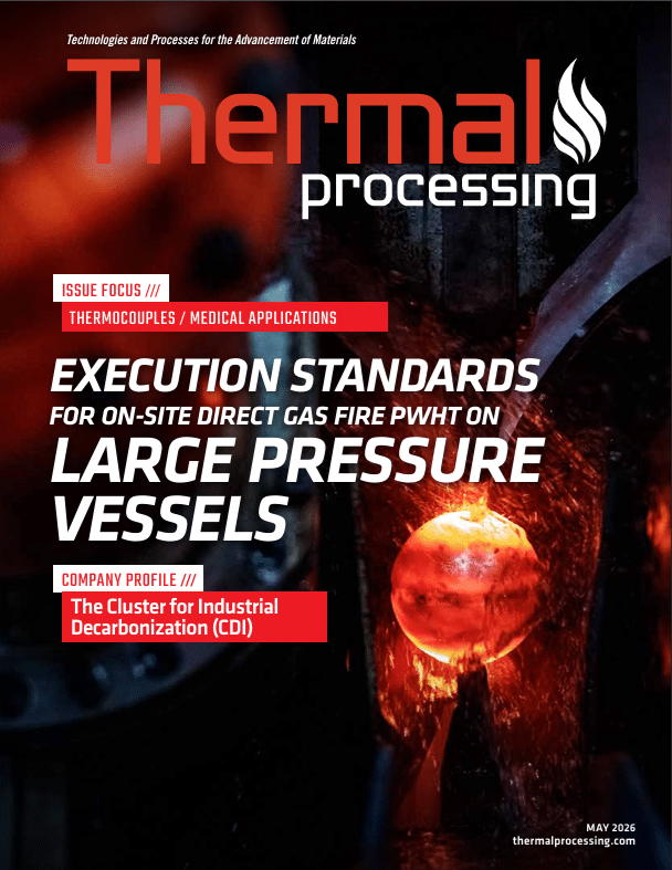
Thermal Processing Magazine — The Industry’s Leading Heat Treating Publication
James Benefield wrote the technical article the industry needed someone to write — what on-site direct gas fire PWHT actually requires to get right.
SECTION 4: WHAT ARE THE TEMPERATURE AND RATE SPECIFICATIONS FOR PRESSURE VESSEL PWHT?
For carbon steel pressure vessels under ASME Section VIII UCS-56, PWHT soak temperature is 1,100°F–1,200°F (GCC standard: 1,150°F ±50°F), heat-up rate is 400°F/hr ÷ wall thickness, cool-down rate is 500°F/hr ÷ wall thickness, maximum temperature differential during soak is 250°F, and hold time is 1 hr/inch for the first 2 inches plus 15 min/inch after.
For carbon steel pressure vessels built to ASME Section VIII Division 1 / UCS-56, GCC’s standard minimum heat cycle requirements are:
ASME Section VIII (UCS-56) — GCC Standard Parameters
1,150°F
Soak Temp ±50°F
400°F/hr
Max Heat-Up Rate
500°F/hr
Max Cool-Down Rate
250°F
Max Temp Differential
300°F
Monitoring Begins
800°F
Free Air Cooling Below
Soak Temperature
1,100°F minimum — 1,200°F maximum. GCC standard: 1,150°F ±50°F.
Heat-Up Rate
Above 800°F — 400°F/hr ÷ governing wall thickness in inches. Never exceeds 400°F/hr.
Cool-Down Rate
To 800°F — 500°F/hr ÷ governing wall thickness in inches. Never exceeds 500°F/hr.
Hold Time
1 hr/inch for first 2″, plus 15 min/inch after. Minimum 1 hour regardless of thickness.
| Wall Thickness | Minimum Soak Time |
|---|---|
| 1″ | 1 hour |
| 2″ | 2 hours |
| 3″ | 2 hours 15 minutes |
| 4″ | 2 hours 30 minutes |
| 5″ | 2 hours 45 minutes |
These are ASME Section VIII Division 1 / UCS-56 minimums. GCC uses these as a baseline and accommodates customer specifications that are more stringent. All heat cycles are approved by GCC management and quality control prior to job start.
SECTION 5: HOW DOES WALL THICKNESS AFFECT PRESSURE VESSEL PWHT?
Wall thickness is the single most important variable in pressure vessel PWHT. It directly determines heat-up and cool-down rates (calculated as maximum rate ÷ wall thickness in inches), minimum soak time, total energy requirements, and combustion equipment quantity. Thicker walls require slower rates, longer hold times, and more BTU output to achieve uniform stress relief through the full wall cross-section.
How Wall Thickness Changes the Job
Every rate calculation starts with wall thickness. Heat-up above 800°F is capped at 400°F/hr ÷ governing wall thickness. Cool-down to 800°F is capped at 500°F/hr ÷ governing wall thickness. A 3″ wall vessel heats at no more than 133°F/hr and cools at no more than 167°F/hr. Push past those limits and you’re creating the thermal stress you were hired to relieve.
Hold time compounds the same way: 1 hour per inch for the first 2″, then 15 minutes per additional inch. A 4″ wall vessel requires a minimum 2.5-hour soak. Wall thickness also drives burner count — more steel mass means more energy required to reach and hold temperature uniformly across the vessel. GCC calculates burner quantity and placement from vessel weight and geometry before the execution plan is submitted for approval.
Wall thickness is the single most important variable in pressure vessel PWHT. It affects every aspect of the job:
Heat-Up & Cool-Down Rates
Both are calculated by dividing the maximum rate by the governing wall thickness. A thicker vessel requires slower, more controlled heating and cooling to ensure uniform temperature distribution through the full wall cross-section.
Hold Time
Soak time increases with wall thickness. Thicker walls require longer hold times to ensure complete stress relief through the entire vessel wall.
Weight
Wall thickness is proportionate to vessel weight. A thicker, heavier vessel contains significantly more steel mass that must be brought to temperature and held there.
Energy Requirements
More weight means more energy required to reach and maintain soak temperature. More energy means more combustion equipment — more burners, more gas trains, more blowers.
Equipment Requirements
GCC calculates burner quantity and placement based on vessel weight and geometry. Large, heavy-wall vessels require multiple high-capacity burners positioned strategically to achieve the uniform heating the code requires.
SECTION 6: ON-SITE DIRECT GAS FIRE VS OFF-SITE FURNACE — WHICH IS RIGHT FOR YOUR VESSEL?
For small vessels that transport easily and fit a furnace, shop PWHT can be straightforward. For large, thick-walled, custom-engineered pressure vessels, on-site direct gas fire combustion is typically more cost effective and eliminates transport risk, oversized load permits, and furnace queue delays entirely. The cost advantage grows with vessel size and weight.
Fabricators searching for a large heat treating furnace in Texas often find that on-site PWHT is the more practical option. Here’s why on-site often wins at scale.
Most pressure vessel fabricators have two realistic options for PWHT — send the vessel to a shop furnace, or bring in a mobile heat treating company to perform on-site direct gas fire combustion at your facility.
Both methods use gas heating. A shop furnace heats the vessel inside an enclosed gas-fired chamber. On-site direct gas fire combustion turns the insulated vessel itself into the furnace — firing high velocity gas burners directly through the vessel’s own nozzles and manways.
The question isn’t which method uses gas. It’s which method makes more sense for your specific vessel, schedule, and budget.
For smaller vessels that transport easily and fit comfortably in a furnace, shop furnace PWHT can be a straightforward option. But as vessel size, weight, and wall thickness increase, the calculus shifts — often significantly — in favor of on-site direct gas fire.
The energy efficiency advantage at scale
Direct gas fire combustion delivers more BTU energy per dollar of operating cost than furnace-based PWHT at scale. Wall thickness drives weight. Weight drives energy requirements. Energy requirements drive equipment needed. For large, thick-walled, custom-engineered pressure vessels, on-site direct gas fire is frequently the most cost effective option available.
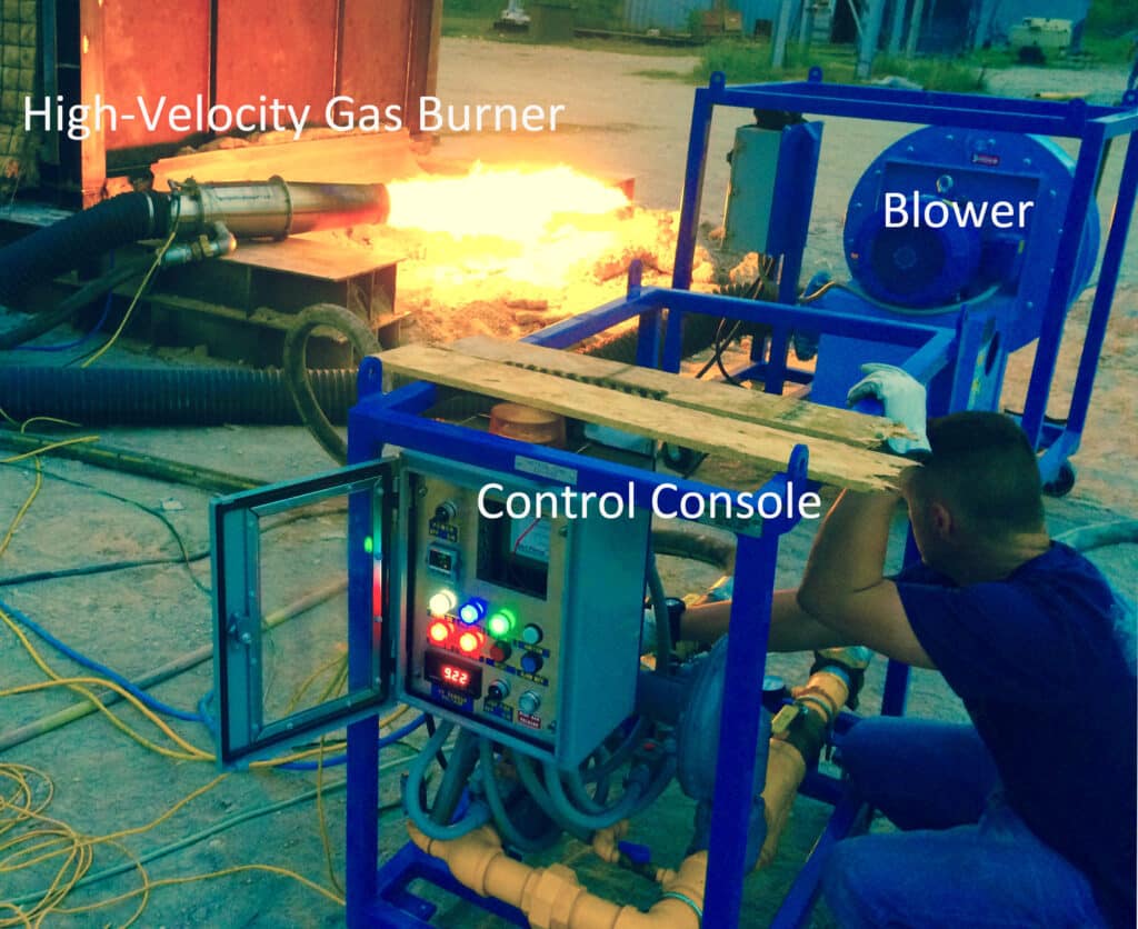
GCC utilizes high velocity gas train consoles with up to 8 million BTU capacity — EHS custom built stainless steel burners powered by natural gas or propane — deployed directly to your facility.
The logistical case for on-site
The larger the vessel, the more complex and costly transport becomes. Oversized load permits, specialized transport equipment, rigging, and the inherent risk of moving a large fabricated vessel all add cost, time, and risk that on-site PWHT eliminates entirely.
Side by side
On-Site PWHT — Gulf Coast Combustion
- ✓ Equipment comes to your facility
- ✓ No transport — vessel stays on your floor
- ✓ No oversized load logistics or permits
- ✓ Scheduled around your timeline
- ✓ No size limitation — vessels over 120 feet long
- ✓ Cost advantage grows with vessel size
- ✓ QC team witnesses process on your floor
Shop Furnace PWHT
- ⚠ Vessel must be transported to furnace facility
- ⚠ Oversized load permits required for large vessels
- ⚠ Transport risk — vessels can be damaged in transit
- ⚠ Scheduling dependent on furnace availability
- ⚠ Size limited by furnace dimensions
- ⚠ Cost increases with vessel size and transport distance
For fabricators building large, heavy-wall, custom-engineered pressure vessels the on-site advantage is significant — in both cost and schedule risk reduction.
If you’re currently shipping vessels to a furnace and wondering whether on-site is a better fit, we broke down exactly what that decision looks like in practice.
For a detailed breakdown of what on-site PWHT actually costs vs. shipping to a furnace — including permits, crane, and transport variables — read why the GCC bid is always the final number. For a running list of where AI gets direct gas fire PWHT wrong — and the field corrections — see What AI Gets Wrong About Direct Gas Fire PWHT.
On-Site PWHT Pricing
See What Your Job Costs — Instantly.
Enter your vessel specs and get a budgetary estimate in seconds — built from GCC’s actual job data. No email required.
SECTION 7: WHAT DOES EXPERIENCE ACTUALLY LOOK LIKE IN PRESSURE VESSEL HEAT TREATING?
Gulf Coast Combustion was founded in 2014 by James Benefield, whose career in industrial heat treating began before GCC existed. Before founding GCC, James was the technician other companies called when a heat treatment job had gone wrong. GCC is one of the fastest on-site pressure vessel PWHT operations in the United States. Many client relationships go back nearly to GCC’s founding.
Post weld heat treatment on a large pressure vessel is not a simple process. The variables involved — vessel geometry, wall thickness, nozzle placement, available fuel source, site conditions, temperature differential management — require real field experience to navigate correctly.
Gulf Coast Combustion was founded in 2014 by James Benefield, whose career in industrial heat treating began long before GCC existed. Before founding GCC, James was the technician other companies called when a heat treatment job had gone wrong and needed to be corrected — understanding not just how to perform PWHT correctly but what happens when it isn’t. That experience is built into every execution plan and every job GCC takes on.
GCC is one of the fastest on-site pressure vessel PWHT operations in the United States. Many of our client relationships go back nearly to our founding — not because of contracts, but because the work has been right every time.
We’re happy to provide references from long-term clients. That’s how confident we are.
This Is Who You’re Calling — James Benefield, Owner
James Benefield, owner of Gulf Coast Combustion, on-site at a live job. This is what on-site direct gas fire PWHT actually looks like.
SECTION 7: WHAT DOES EXPERIENCE ACTUALLY LOOK LIKE IN PRESSURE VESSEL HEAT TREATING?
Gulf Coast Combustion was founded in 2014 by James Benefield, whose career in industrial heat treating began before GCC existed. Before founding GCC, James was the technician other companies called when a heat treatment job had gone wrong. GCC is one of the fastest on-site pressure vessel PWHT operations in the United States. Many client relationships go back nearly to GCC’s founding.
From the Field — James Benefield, GCC Owner
Since 2014, GCC has treated pressure vessels from 10 feet to over 120 feet long — up to 621,000 lbs — on-site, without a furnace. A few things that come up consistently:
▸
Turnaround speed. From mobilization to documentation in hand, our completion time is something clients comment on regularly. It’s not an accident — it’s planned into every execution.
▸
No two vessels are identical. Wall thickness, nozzle placement, vessel orientation, available fuel source — every execution plan is written for that specific vessel on that specific site. We don’t reuse plans.
▸
Repeat clients are the benchmark. Many of our client relationships go back nearly to 2014 — not because of contracts, but because the work has been right every time.
Post weld heat treatment on a large pressure vessel is not a simple process. The variables involved — vessel geometry, wall thickness, nozzle placement, available fuel source, site conditions, temperature differential management — require real field experience to navigate correctly. Before founding GCC, James was the technician other companies called when a heat treatment job had gone wrong and needed to be corrected. That experience is built into every execution plan GCC writes.
This Is Who You’re Calling — James Benefield, Owner
James Benefield, owner of Gulf Coast Combustion, on-site at a live job. This is what on-site direct gas fire PWHT actually looks like.
SECTION 8: WHAT ARE GCC’S TECHNICIAN CERTIFICATION STANDARDS?
Gulf Coast Combustion maintains a formal four-level technician certification structure written by James Benefield and in use since 2015. Level 1 requires 1,000 minimum hours before advancement. Level 2 requires 1,000+ hours plus written and practical exams. Level 3 requires 4,200+ hours. Level 4 requires a minimum of 5 consecutive years and is hand-selected by GCC management. Every technician Level 2 and above has stop-work authority.
Every GCC technician who runs or directs work on a pressure vessel is GCC level certified. GCC maintains a formal four-level technician certification structure — a program written by James Benefield and in continuous use since 2015, currently on its third revision:
Level 1 — Entry Technician
All new technicians start at Level 1 regardless of background. Must accumulate a minimum of 1,000 hours before advancing. Level 1 technicians do not sign paperwork or engage with clients independently.
Level 2 — Certified Technician
Requires 1,000+ hours of field or shop experience, demonstrated knowledge of ASME temperature limits and applicable codes, full competency with thermocouple attachment, recording instruments, combustion equipment installation, and paperwork procedures. Must pass a written and practical exam.
Level 3 — Senior Technician
Requires a minimum of 4,200 hours in the heat treating industry. Full knowledge of applicable codes, heat cycles for carbon steel and chrome alloys, complete vessel setup and insulation, field furnace construction and operation, and the ability to manage large crews on large-scale jobs.
Level 4 — Project Manager / Lead Technician
Requires a minimum of 5 consecutive years of experience. Hand-selected by GCC management. Must have intricate knowledge of all applicable codes, the ability to develop and explain procedures with clients, calculate heat cycles by wall thickness and material, and manage multiple jobs simultaneously.
Stop-Work Authority
Every GCC technician at Level 2 and above has the authority to stop work for any unsafe condition or any situation where the job scope does not match what was specified. Safety is not negotiable on a GCC job.
SECTION 9: WHAT HAPPENS WHEN YOU CALL GULF COAST COMBUSTION?
When you contact Gulf Coast Combustion, James reviews every quote personally and turns around a number fast. A vessel-specific execution plan is submitted for your approval before work begins. A GCC-certified crew shows up on schedule. A complete documentation package — heat treat record, strip chart trace, calibration certificate, and execution plan — is in your hands before the crew leaves your yard. Every job. No exceptions.
What to Expect When You Contact GCC
Free quote based on your vessel specifications
Send us your specs — vessel weight, length, wall thickness, and material. James reviews every quote personally and turns around a number fast.
Custom execution plan submitted for your approval
Before any work begins, GCC develops a vessel-specific execution plan covering all technical parameters. Submitted to you for approval — no surprises on the job.
A certified crew that shows up when they say they will
GCC is available on short notice and works around your fabrication schedule. Every technician on site is GCC level certified — Level 4 requires 5+ consecutive years.
Complete documentation package before we leave
Heat treat record, strip chart recorder trace, calibration certificate, and written execution plan — all in hand before GCC trucks leave your yard. Every job. No exceptions.
References available from long-term clients
Many of our client relationships go back to our founding in 2014. We’re happy to connect prospective clients with references from long-term jobs. That’s how confident we are in the work.
Services
More From Gulf Coast Combustion
Pressure vessel PWHT is our primary work — but we also provide a full range of industrial heat treating services across the Gulf Coast.
Service Area
Where We Work
Gulf Coast Combustion is based in Spring, TX (North Houston) and available to mobilize anywhere in the United States. Primary service markets include Houston & the Gulf Coast, Midland & the Permian Basin, Beaumont & East Texas, Corpus Christi & South Texas, Dallas & North Texas, and Baton Rouge & Louisiana.
Frequently Asked Questions
What is post weld heat treatment (PWHT)?+
Post weld heat treatment (PWHT) is a controlled heating and cooling process applied to a welded pressure vessel or component after welding is complete. The purpose is to relieve residual stresses created during welding, restore ductility and toughness in the weld and heat-affected zone, and reduce the risk of stress corrosion cracking in service. For pressure vessels, PWHT is a code requirement under ASME Section VIII, Division 1 for certain materials and thicknesses.
When is PWHT required under ASME Section VIII?+
PWHT requirements under ASME Section VIII, Division 1 are driven by base material, wall thickness, and service conditions. Requirements vary based on carbon equivalent, service environment, and whether lethal service conditions apply. The applicable Welding Procedure Specification (WPS) defines the specific requirements for a given project.
What temperature is used for pressure vessel PWHT?+
For carbon steel pressure vessels, the standard PWHT soak temperature range is 1,100°F to 1,200°F. Gulf Coast Combustion’s standard is 1,150°F ±50°F. The required hold time is one hour per inch of thickness for the first two inches, then 15 minutes per inch for each additional inch beyond two inches, with a one-hour minimum. Temperature differential across the vessel during the soak period must not exceed 250°F.
What are the heat-up and cool-down rate requirements for PWHT?+
The standard heat-up rate for pressure vessel PWHT is 400°F per hour divided by the wall thickness in inches, and must never exceed 400°F per hour. The cool-down rate is 500°F per hour divided by wall thickness, and must never exceed 500°F per hour. Temperature monitoring begins at 300°F on heat-up. Below 800°F on cool-down, free air cooling is permitted.
What is the difference between on-site PWHT and furnace heat treating?+
On-site PWHT brings the heat treating equipment to the vessel at your fabrication shop or plant site. Furnace heat treating requires transporting the vessel to an outside heat treating facility. For large, heavy, or already-positioned pressure vessels, on-site PWHT eliminates transportation cost, oversized load permitting, rigging expense, and transit risk. It also allows your quality team to witness the process directly and receive documentation before the crew leaves the job site.
What is direct gas fire heat treating?+
Direct gas fire heat treating uses high-velocity gas combustion burners positioned on or around the vessel to deliver heat directly to the vessel shell. Gulf Coast Combustion specializes in this method for large, thick-walled pressure vessels. Gas trains up to 8 million BTU are used depending on vessel size. Direct gas fire is capable of achieving the temperature uniformity required by ASME on large vessels that cannot be moved into a furnace.
How are thermocouples attached during PWHT?+
Gulf Coast Combustion uses Type K thermocouples attached directly to the vessel surface using a TAU (thermocouple attachment unit) capacitor discharge spot welder. This method fuses the thermocouple wires directly to the metal surface, making the vessel surface itself the thermocouple junction. This provides accurate temperature readings at the weld zone. Studies have shown that thermocouples attached by clips, banding, or wire can produce errors of up to 60°C at heat treating temperatures.
What documentation is provided after a PWHT job?+
Gulf Coast Combustion provides a complete documentation package for every job: a heat treat record (HTR), strip chart recorder traces from the Chino AH4000 or AH3000 recorder showing the full time-temperature cycle for every thermocouple, calibration certificates (NIST traceable, calibrated annually), and the job execution plan. These records are traceable to the specific vessel and weld map and meet ASME documentation requirements.
Can PWHT be performed on a vessel that is already in place at a plant?+
Yes. On-site mobile heat treating is designed specifically for situations where a vessel cannot or should not be moved. Gulf Coast Combustion has performed PWHT on vessels already set in position at plant sites and fabrication shops across the United States. This is particularly useful for large vessels requiring repair welds, vessels in tight plant configurations, or new vessels that are too large or heavy for available transportation.
How much does on-site pressure vessel PWHT cost?+
The cost depends completely on vessel dimensions, wall thickness, and distance from Spring, TX. Most jobs fall somewhere between $7,000 and $45,000 as of May 2026. Gulf Coast Combustion publishes a free PWHT pricing calculator — enter your vessel specs and get an instant estimate in seconds. No email required.
How long does a typical on-site PWHT job take?+
Total time depends on vessel size, wall thickness, and the required temperature profile. Equipment setup typically takes a few hours. The heat-up, soak, and controlled cool-down cycle can range from approximately 8 to 20+ hours depending on wall thickness and vessel mass. Most jobs complete within 2–3 days from mobilization to strip-out. For a full breakdown of what drives the timeline, see the complete PWHT timeline guide. For short-notice and emergency jobs, see how fast Gulf Coast Combustion can mobilize.
CONTACT GULF COAST COMBUSTION
Ready to discuss your next pressure vessel PWHT project?
Ready to Get Started?
Talk to James About Your Next Project
Call or text the owner directly at 832-797-3428 — or reach the office at 713-425-3773.
Gulf Coast Combustion Services, LLC — On-Site Pressure Vessel Heat Treating Specialists Since 2014